User guide
TotaLite 3D turns the 2D observations of two TotaLite sensors into a single 3D displacement for every target. This guide walks through the on-site setup, then the Setup and Data tabs of this app.
1 · On site — place and survey
Position both sensors
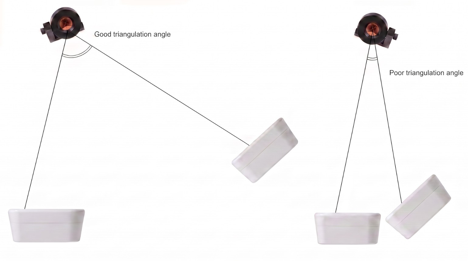
Mount the two TotaLite sensors so that both observe the targets under a favorable angle.
Survey the geometry
Use a total station (or equivalent) to establish the 3D positions of every target and both TotaLite sensors. Coordinates are in metres. You don't need survey-grade precision here — see how accurate do I need to be?
- The reference point of a sensor sits roughly 1 cm behind the front glass. Being a few centimetres off is fine.
- For a two-prism target (two prisms rigidly connected to track one mounting point), survey the centre of gravity of the prism pair. Aim each prism at its own TotaLite, and add a separating shield so neither sensor sees both prisms.
Set a 5-minute interval
Configure both sensors to measure at a 5-minute interval. Motion is assumed slow, so two measurements taken within 5 minutes are treated as synchronized — this is what lets the two 2D views be combined into one 3D result.
2 · Setup tab — build the project
Create and open a project
Go to the TotaLite 3D calculator and create a new project from the projects list and open it.
Import the geometry (CSV)
Upload your surveyed coordinates as a CSV file with the headers name, x, y, z (values in metres).
- If a row's name matches a sensor you own (e.g. TotaLite_32421), it is automatically linked to that sensor.
- Otherwise, use the per-row device / target buttons to switch a row between target or device.
- Confirm you have both sensors configured as devices and linked to the correct physical position.
You can't edit X/Y/Z in the table. To change coordinates, edit the CSV and upload it again.
Choose the reference target
Indicate which target is the reference target. It is used only to correct for the sensors' yaw — pitch and roll come from each sensor's internal tilt sensor.
Set the baseline
Select a baseline timestamp, then press Set baseline. The app finds data from both sensors near that timestamp and initializes the sensor poses.
A frustum appears for each sensor in the 3D scene and all four readiness boxes turn green. The calculator can now process the raw sensor data into 3D displacements.
3 · Data tab — plot and export
Choose a time range
Press Open data view to open the Data tab, then set a start time (auto-filled to the baseline time) and, optionally, an end time. Then either start plotting or download the data for that range.
There is no limit on the range — a wide window can produce very large plots.
Results are computed on demand
- Change the setup and any results you fetch here will change accordingly.
- Because everything is recomputed on demand, improvements to our algorithms can also change results over time — so re-plotting the same range later may differ slightly even when your setup is unchanged.
Reference
What's a favorable angle?
This is the angle at the target: from TotaLite A → target → TotaLite B. If it's sharp (say 1°), depth is effectively unobservable and infinitely noisy. Ideally this angle is 90°.
In 2D, accuracy is about 1 mm at 40 m, scaling linearly with the distance to the TotaLite. In 3D, the error on the added (depth) dimension depends strongly on the angle:
| Angle at target | Depth error |
|---|---|
| 90° (ideal) | ≈ 1× |
| 60° | ≈ 2× |
| 40° | ≈ 3× |
| 20° | ≈ 6× |
Below 40° the error grows exponentially — it is already ~6× larger at 20°.
How accurate do I need to be?
The surveyed 3D setup is used to (1) auto-initialize tracking — matching the 2D observations to the 3D targets — and (2) use the geometry to translate the two 2D displacements into one 3D displacement.
For displacement, the accuracy of the geometry is not crucial. An inaccurate geometry would give poor absolute coordinates with a systematic error — but for small displacements that systematic error is nearly identical at both epochs and cancels out, so the displacement stays very accurate.
Be 1% accurate, capped at 10 cm.
| Distance to device | Accuracy needed |
|---|---|
| ≥ 10 m | 10 cm |
| 5 m | 5 cm |